Solving the Dog-Bunny Puzzle with Program Verification Technology
As a high schooler in the 70’s, my father enjoyed playing the Star Trek game written for the Sigma 7 mainframe. You play as the Enterprise surrounded by Klingon ships, and to shoot them down you have to look at a grid and figure out which angle (in degrees) to fire at.
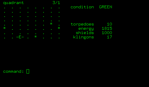
It was fun right until he learned trigonometry.
Three days ago, Conrad Barski, creator of the absolutely delightful book/comic Land of Lisp, took the Internet by storm with a new puzzle game. In this puzzle, three characters move between rooms and press buttons, where each button closes or opens other doors. At least, that’s how it might appear in a traditional video game. Phrased that way, it may remind you of many other games; I’m reminded of the famous Flash game Fireboy and Water Girl and the obscure student project Lineland. But in its actual presentation, the Dog-Bunny Puzzle abstracts this mechanic into a thing someone can understand with no instructions in 60 seconds, while also being surprisingly difficult.
I spent a minute or two playing around and discovered that it would actually take serious thinking to solve it. I was about to put it down to get back to my work, writing design challenges for software engineers, when I realized this puzzle could fall to a sledgehammer a bit less humdrum than trigonometry, something I first learned about in a lecture on how to automatically fix bugs in concurrent programs.
You see, the puzzle could be modeled with something called a Petri net. And then I could run a Petri-net solver to solve the puzzle.
In fact, modeling it is so straightforward that I’d go so far as to claim the puzzle is a Petri net.
Following in my father’s footsteps, I shall now proceed to destroy the fun in this puzzle by replacing it with an intellectual challenge.
What is a Petri Net?

A Petri net is a graph with a bunch of tokens on each node. When certain conditions are satisfied, you are allowed to move tokens from one node onto another node. If this already sounds like the Dog-Bunny Puzzle, then, well, I did say the puzzle is a Petri net, right?
They were supposedly invented by Carl Adam Petri when he was 13, and are widely used in the field of formal verification. Unlike Petri dishes, invented a century earlier, they cannot be used to grow bacteria. But they can be used to model cellular activity in bacteria.
A Petri net has three components: places, transitions, and tokens. Consider this Petri net:

- The four circles are places.
- The small black circles are tokens.
- The rectangles are transitions.
- To fire a transition, you remove one token from each of the incoming places, and add a token to each of the outgoing places. So, in this picture, to fire T1, you would remove a token from place cp1 and add a token to place p1.
- If all of the incoming places for a transition have tokens on them, then it is possible to fire that transition, and we call it enabled. Otherwise, it is disabled. In this picture, T1 is enabled, while T2 and T3 are disabled.
And….that’s basically it. But they can do a lot. Places can represent lines in a program, states in a protocol, or molecules in a chemical reaction. Tokens can represent which line a thread is on, or some shared resource like a lock. And then the same general tools and algorithms can be applied to each of them.
There are several bajillion extensions to the basic Petri net model. For this puzzle, we need colored Petri nets. All that means is that there are now two types of tokens instead of one: dog tokens and bunny tokens.
I went searching for a colored Petri net solver, and found what looks to be the only game in town: a pretty serious package called CPN Tools. This was going to be fun. I eagerly went to the downloads page and found the Mac section.
We recommend you to download the latest stable Windows version of CPN Tools and run it using a virtual machine. See instructions for doing this on a Mac here (the instructions for doing so on Linux should be similar). You can also run CPN Tools using Wine.
Fun indeed.
Modeling the Dog-Bunny Puzzle in CPN Tools
You ever hear complaints about UIs designed by programmers? You know you’re using one when there are two colors and two hundred buttons.
CPN Tools feels more like it was written by someone whose parents forced them to go to tech school instead of art school. The only thing you can do is drag pictures onto the screen, and the primary effect of doing so is to cover your window in pastel-colored bubbles. While conformist programs let you save by either going to File->Save or clicking an icon of a floppy disk, in CPN tools you get to click an illustration of a Petri net moving onto a floppy disk, and then drag it onto the thing you want to save. A little green comic-book speech bubble pops up to tell you your save is successful, except that there’s no actual speech in the bubble, because artwork that speaks to the head misses the soul, or something. The manual paints a sweeping Impressionistic picture of the software, with the details left to the reader’s imagination.
But enough of that. Time for you to sit back and learn some formal methods.
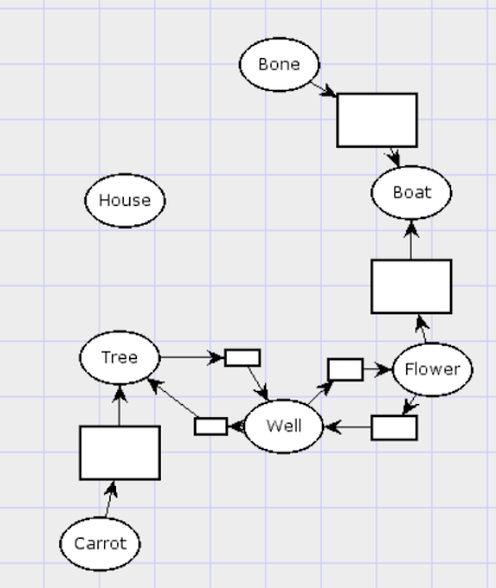
The first step is to define the places. We’ll have one place in the Petri net for each place in the Dog-Bunny Puzzle. I’ll set them up with roughly the same geometry as in the puzzle.

Now we start on the transitions. There are unconditional unidirectional transitions from the Bone and Flower to the Boat, and from the Carrot to the Tree. That is, a dog or bunny can move from the Bone to the Boat at any time, no matter what, but not vice versa. These are transitions with one incoming and one outgoing arc each, removing a token from one and adding it to the other.

There are unconditional bidirectional edges between the tree and well, and the well and flower. That means, at any time, a dog or bunny can move between these in either direction. Petri nets don’t really have bidirectional transitions, so we have to model these as a unidirectional transition in each direction.
Now we turn to the conditional edges. There’s an edge from the House to the Bone that can only be crossed if something is at the carrot. This can be modeled: there’s a transition that removes a token from the House and Carrot, and then adds tokens to the Bone and Carrot. So the net effect of firing this transition is to move a token from the House to the Bone, but it’s only enabled if something is on the Carrot. I’ll call the arcs between this transition and the carrot “enablement arcs.”
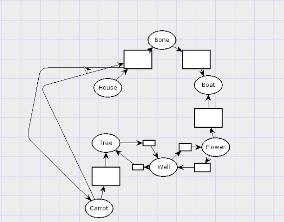
This is the point where the model starts to get graphically ugly even as it remains conceptually simple. There’s a reason the puzzle just represents these relationships with text. From now on, I’ll be drawing all these enablement arcs in white so you can pretend they’re not there. Let’s finish these: There transitions from House to Boat and vice-versa which require something on the tree, and ones between Tree and House which require a token both on Bone and Flower.

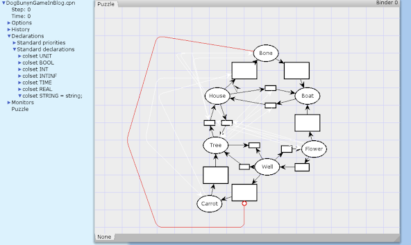
Now, the last transition is a little different: A token can move from Well to Carrot only if there is nothing on Bone. This one sounds painful to model the way we’ve been working. One option is to add a transition from Well to Carrot enabled by House, and another one from Well to Carrot enabled by Boat, and so on for every place except for Bone. Fortunately, CPN Tools supports inhibitor edges: I draw a transition from Well to Carrot with an inhibitor edge from Bone, and it behaves exactly the way we want. Here’s the model, with the inhibitor edge in red, and all enablement edges in white. I’ll include a little bit more of the UI in the screenshot this time.
Now, it’s time to add the tokens. The “colors” of tokens in CPN tools can have a lot of structure: they can be numbers, booleans, or richer data structures. But here, we just need two types of tokens: dogs and rabbits. These tokens are interchangeable except for the victory condition, so they’re really two variants of the same type, at least as far as CPN Tools is concerned. The “Declarations” pane to the left has a standard list of “color sets.” I’ll add a new one:
colset ANIMAL = union DOG | RABBIT;
Now it’s time to add the dog and rabbit tokens to the graph. We’ll need to change the type of every place to ANIMAL, and then we can add the tokens. How do we do it? If you guessed “Press the TAB key twice and then type 1`RABBIT”, being careful not to balance the backquote, then you are absolutely right.

CPN Tools at this point has decided that my model must be for some kind of performance, and decided it needs an accompanying laser show.
The reason for the errors on each arc is that, because tokens are no longer interchangeable, when tokens enter and leave a transition, I need to specify which is which. If I have a dog on the House, I need a way to specify that the transition moves the dog to the Bone when there’s a rabbit on the Carrot, not that it moves the rabbit to the Bone and the dog to the Carrot.
To do this, we declare three variables under the ANIMAL color set.
   var mover : ANIMAL;
   var constraint1 : ANIMAL;
   var constraint2 : ANIMAL;
Now, we label every single arc with one of these variables. If a transition has incoming arcs labeled mover and constraint1, then the token which travel across those arcs get bound to mover and constraint, respectively. Then there are outgoing arcs also labeled mover and constraint1, indicating which token goes where. So we’ll label most arcs with mover, but enablement arcs with constraint1 and constraint2.
One problem though: I can’t find a way to hide the labels. To save space in the diagram, I’ll rename these variables to p, q, and r.

And…the model is done! We can now plan with it in CPN Tools’s simulator mode, and see that it follows the same rules as the original Dog-Bunny puzzle.
One last thing though: Before we can start to use the solving features of CPN tools, we need to give each transition a unique name. I’ll just name them a, b, c, d, etc.

Solving the Dog-Bunny Puzzle with CPN Tools
It is now time to solve.
Every arrangement of tokens on places forms a state. In the start state, there is a rabbit on the House, a rabbit on the Boat, and a dog on the Tree. In one possible successor state, there are two rabbits on the House. In a different successor state, there are two rabbits on the Boat. From the start state, we seek to reach a state with the rabbits on the Carrot and the dog on the Bone.
You might think we could try dragging the rabbit tokens to the Carrot, the dog tokens to the Bone, and then ask “How do we reach this state?” Or perhaps by typing a query into some kind of query box. But that would be neither artistic nor technical enough.
We make the procedure technical by writing code in asking for which state has the properties of the dog and rabbits being in their proper positions. We use Standard ML, as the language endorsed by a certain breed of university professor who thinks they know programming better than you do. The important part of this snippet is the lambda beginning on the third line; the rest is just telling it to actually search the state space and give me a list of results.
SearchNodes (
 EntireGraph,
  fn n => [DOG] = (Mark.Puzzle'Bone 1 n)
          andalso
          [RABBIT, RABBIT] = (Mark.Puzzle'Carrot 1 n),
 10,
 fn n => n,
 [],
 op ::)
We then run the code using an out of the box idea, which makes the code one with the image: we type it into an arbitrary textbox and right-click “Evaluate ML.”
And thus, we learn that it is possible to reach a state with the desired property, and it is called state 150. Woohoo!
Not only that, but by similarly running more code
NodesInPath(1, 150)
We learn the sequence of states needed to get there is:
[1,4,8,13,17,20,23,26,28,33,42,55,70,
86,98,105,110,113,116,118,123,130,137,
142,145,148,150].
We learn that the solution to the puzzle requires 26 moves. All that’s left is to learn what these numbers mean.
You might think we could just click a button and it would show you the state that one of these numbers means. That is close, but it has the problem of not feeling like Photoshop, so instead you need separate clicks to first select the “Set Petri net to state 4” tool and then to tell the computer system, that, yes, the reason you selected this tool is to see state 4.
If that’s too slow, well, you also have the option of reading the states like this.

But now, after spending more time trying to read the generated solution than some people took to solve it from scratch, I have it! And now my animals are well-fed and happy.

- Time I spent to solve this puzzle: 3 hours
- 10 minutes modeling, 2 hours 50 minutes figuring out CPNTools’s interface
- Time spent by the 8 year-old daughter of a random commenter: 2 minutes
Conclusion
I don’t see myself using CPN Tools again. It’s too programmatic to be a good GUI tool, and too GUI-based to be a good programmatic tool. Hopefully in the future if I use Petri nets, I’ll only need normal ones, not colored. That opens up quite a few programming libraries, such as the SNAKES library in Python. Some of them might actually implement the clever solving algorithms we’ve had for 40 years, as opposed to CPN Tools, which appears to just brute force it.
Funny enough, while I know of a use of Petri nets in practical programming tools (productivity, not verification) recently, I’m personally responsible for killing it. Hoogle+ is a tool that uses Petri nets to come up with small programs of a desired type. My most recent paper introduces a new algorithm (not based on Petri nets) which solves the same problem 8x faster despite an implementation just a tenth the length.
But, regardless, now I’m more experienced with a technique that can solve loads of problems. And so are you.
I have released my CPN Tools file for this post here.

Next to your first Petri net diagram with the places, transitions, and tokens, you say, "The three big circles are places." However, I don't see three big circles, I in fact see four (4) big circles (cp1, cp2, p1, & p2). Is this is typo in your bulleted list, or am I misunderstanding something?
ReplyDeleteThanks! Yes, that is a mistake, which I have now fixed. I likely started writing that explanation with a different pictures which did have three big circles, not 4 little circles.
DeletePetri nets are also a great way to model dependency graphs, e.g. for build systems. Most build systems make targets first-class and processes secondary (and therefore struggle when a process updates several targets) or make processes first-class and targets secondary (and then struggle when several processes can potentially update a target). Petri nets handle both these cases and more elegantly. Sadly the only build system I know of which uses them (without using that name) is Tup.
ReplyDeleteVery interesting. I get the problem with making processes the main object. What's the problem with making targets the main object?
DeleteLet's take a concrete example. The OCaml compiler takes a compilation unit X.ml and produces files X.cmo (compiled bytecode) and X.cmi (a compiled description of the unit's interface). Suppose some other unit Y needs to be linked against X. To compile Y, we'll need both Y.ml and X.cmi, but not X.cmo. Conversely, we can link X.cmo and Y.cmo into an executable without looking at X.cmi or Y.cmi. You have various ways of handling this in a targets-only build system, none of them good:
Delete- Ignore the .cmi files, and tell the build system that Y.cmo depends on X.cmo. Now implementation-only changes to X force you to recompile Y too, and also your build breaks if someone deletes X.cmi but leaves X.cmo alone. Something similar goes wrong if you ignore the .cmo files.
- Try to make each process produce a single output from which the actual outputs can be extracted one-by-one - for instance, by specifying a per-process output directory (many compilers will not let you do this), or by tarring them up into a single file (at the cost of extra runtime work and build-system complexity).
- Mark X.cmi as depending on X.cmo but with no build process specified. Your build graph no longer lies to you, but your build still breaks if someone deletes X.cmi.
The debate over how to handle this problem pretty much killed the redo project.
I see. So, it's the general problem that Petri nets can handle multiple alternatives of things with multiple dependencies (as can tree automata), but normal graphs can't.
DeleteYes, I think so. I hadn't heard of tree automata before - thanks!
DeleteTree automata are great.
Deletehttps://www.youtube.com/watch?v=J7P1zjYpIKw&list=PLyrlk8Xaylp4ee6ZAtFD9XMD2EZ02K9xK&index=37
https://www.jameskoppel.com/files/papers/ecta.pdf